
In this second part of my maze solver build I’ll go through the final PCB making, mounting all the parts onto a chassis and testing the robot.
So far I’ve selected a piece of acrylic to use as the chassis of the robot. It’ll have two tiers. On the upper tier the batter and main circuit board will be mounted and on the lower tier the motors, wheels and line sensor module will be mounted.
Here are some pictures of the completed circuit board:
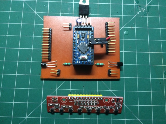
I went with two 2N2222A transistors instead of a H-bridge IC since this helped keep the size of the board small and also since I don’t plan on changing the direction of the wheel, the H-Bridge would’ve been overkill.
I will update this part once the chassis is complete and the robot is ready for testing!
Here are some pictures of the completed chassis:


First part of the build process here.
